Dillon Model U Force Gauges
The Model U Force Gauge is an accurate (±1% of full range) mechanical compression-measurement instrument. Its slim-line design has repeatedly proven valuable in installations where space is at a premium.
The versatility of this simple instrument is demonstrated by the fact that is can be used as a hand-held device, permanently mounted on a flat surface, or used in test fixtures.
How the U Force Gauge Works
The Dillon Model U Force Gauge employs a deflection beam machined from aircraft quality alloy steel and heat treated to develop optimum strength and spring characteristics. A precision dial indicator is mounted at the null point of this beam.
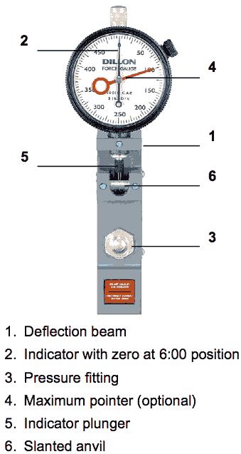
Compression force is normally applied against a single pressure fitting mounted on the upper half of the beam. (For accurate calibration, designate the type of pressure fitting you wish to use with the U Force Gauge. They are of four types: domed, cupped, flat, or a flat nylon insert. Flat bottom gauges require only one fitting.)
When load is exerted, the beam moves downward causing a slanted anvil on the free end to push against the indicator plunger. The indicator reading is a direct representation of the applied load.
Dillon offers a capacity for every job
U Force Gauges are available for measurement in pounds or kilograms. There are 6-pound capacities ranging from 25 x .25 to 5,000 x 50 lb. The 4 kilogram capacities range from 10 x .1 to 500 x 5 kg.
Dillon also offers high-capacity gauges with pounds capacities from 500 to 5,000 lb and a metric model with a capacity of 500 kg. High- capacity gauges all have flat-bottom design, and each includes one pressure fitting of your choice.
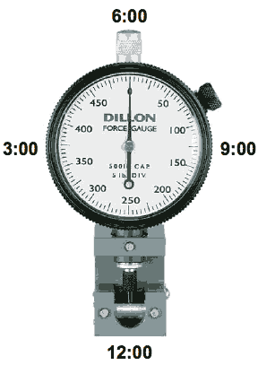
Zero Position– The zero position on the indicator dial can be factory positioned at 12 o’clock, 3 o’clock, 6 o’clock, or 9 o’clock. The standard position is the 6 o’clock position.
Maximum pointer–Model U Force Gauges can include a maximum pointer which remains at peak load until it is reset.
Shockless dial indicator–Offers added protection in applications where force is applied or released rapidly.
Dial orientation–The dial indicator can be factory positioned at 0° (standard), 90°, 180°, 270° clockwise. Photos on this page show standard dial orientation.
Note: maximum pointer and shockless dial indicator cannot be offered on the same unit.
| Low-Range Flat-Bottom Model U Force Gauge | |||||||||||||||
|---|---|---|---|---|---|---|---|---|---|---|---|---|---|---|---|
| Part No. | lbs. | Part No. | Kilograms | in” (mm) | |||||||||||
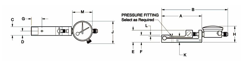
| A | B | C | D | E | F | G | H | J | K | L | M | ||||
| 30354-0017 | 25 x .25 | 30354-0066 | 10 x .1 | 3.28” (83.3) | 5.50” (139.6) | .73” (18.5) | .36” (9.1) | .97” (24.6) | .56” (14.2) | .90” (22.8) | 1.40” (35.5) | 1.87” (47.5) | .46” (11.7) | .094” (2.4) | 1.67” (42.4) |
| 30354-0033 | 100 x 1 | 30354-0082 | 50 x .5 | 3.28” (83.3) | 5.50” (139.6) | .73” (18.5) | .36” (9.1) | .97” (24.6) | .56” (14.2) | .90” (22.8) | 1.40” (35.5) | 1.87” (47.5) | .46” (11.7) | .094” (2.4) | 1.67” (42.4) |
| 30354-0058 | 250 x 2.5 | 30354-0090 | 100 x 1 | 3.28” (83.3) | 5.50” (139.6) | .73” (18.5) | .36” (9.1) | .97” (24.6) | .56” (14.2) | .90” (22.8) | 1.40” (35.5) | 1.87” (47.5) | .46” (11.7) | .094” (2.4) | 1.67” (42.4) |
| High-Range Flat-Bottom Model U Force Gauge | |||||||||||||||
|---|---|---|---|---|---|---|---|---|---|---|---|---|---|---|---|
| Part No. | lbs. | Part No. | Kilograms | in” (mm) | |||||||||||
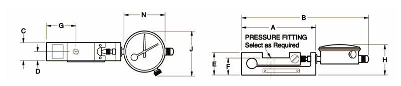
| A | B | C | D | E | F | G | H | J | N | ||||||
| 30482-0020 | 500 x 5 | - | - | 3.87” (98.0) | 6.75” (171.3) | .98” (24.9) | .49” (12.4) | 1.25” (31.5) | .92” (23.6) | 1.52” (38.6) | 1.67” (42.4) | 2.44” (63.5) | 2.25” (57.2) | ||
| 30482-0053 | 1,000 x 10 | 30482-0079 | 500 x 5 | 3.87” (98.0) | 6.75” (171.3) | .98” (24.9) | .49” (12.4) | 1.25” (31.5) | .92” (23.6) | 1.52” (38.6) | 1.67” (42.4) | 2.44” (63.5) | 2.25” (57.2) | ||
| 30478-0034 | 5,000 x 50 | - | - | 4.74” (120.1) | 7.94” (201.5) | .98” (24.9) | .49” (12.4) | 1.72” (43.7) | 1.41” (35.5) | 2.06” (52.3) | 2.06” (52.3) | 2.88” (72.8) | 2.75” (69.9) | ||